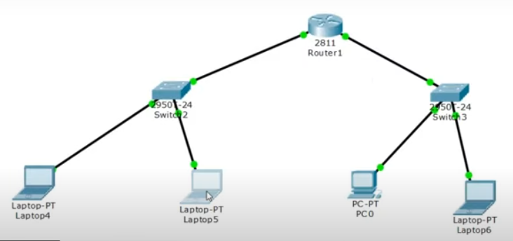
In today’s tutorial, we’ll explore how to implement Dynamic Host Configuration Protocol (DHCP) using Cisco Packet Tracer. Previously, we manually assigned IP addresses to each device. DHCP simplifies this process by automatically distributing IPs—once you define the network ranges and subnet masks, everything else happens behind the scenes. Don’t forget to subscribe to my YT channel
Setting Up the Network Devices
Let’s begin by building our topology:
- Add a Cisco 2811 router.
- Place two 2950 switches.
- Attach two PCs and two laptops (or any end devices) to the switches.

Connecting Devices with Copper Straight-Through Cables
Use copper straight-through cables to establish connections:
- Connect the first PC’s FastEthernet0 to FastEthernet0/1 on Switch1.
- Connect the first laptop’s FastEthernet0 to FastEthernet0/2 on Switch1.
- Repeat similar connections for the second pair of devices on Switch2.
- Finally, link Switch1 to Router Fa0/0, and Switch2 to Router Fa0/1.
Once done, the switch–router links should turn green, indicating they’re up and running.
Configuring Router Interfaces
Access the router’s CLI (Configuration Terminal mode) to set up interfaces:
Interface Fa0/0
arduinoCopyEditRouter> enable
Router# configure terminal
Router(config)# interface FastEthernet0/0
Router(config-if)# ip address 192.168.0.1 255.255.255.0
Router(config-if)# no shutdown
Router(config-if)# exit
Router(config)# do write memory
This assigns the IP and ensures the interface is active and saved.
Enabling DHCP on Fa0/0
Now, activate DHCP for the 192.168.0.0/24 subnet:
arduinoCopyEditRouter(config)# ip dhcp pool NET1
Router(dhcp-config)# network 192.168.0.0 255.255.255.0
Router(dhcp-config)# exit
This creates a DHCP pool named NET1 using the specified network range.
Configuring Interface Fa0/1
Repeat similar steps for the second network interface:
arduinoCopyEditRouter(config)# interface FastEthernet0/1
Router(config-if)# ip address 192.168.1.1 255.255.255.0
Router(config-if)# no shutdown
Router(config-if)# exit
Router(config)# do write memory
Enabling DHCP on Fa0/1
Set up DHCP for the 192.168.1.0/24 subnet:
arduinoCopyEditRouter(config)# ip dhcp pool NET2
Router(dhcp-config)# network 192.168.1.0 255.255.255.0
Router(dhcp-config)# exit
The pool NET2 now manages IPs for all devices connected to Fa0/1.
Verifying DHCP Allocation on PCs and Laptops
Switch to each connected device:
- Go to Desktop → IP Configuration
- Set IP allocation to DHCP
- Watch as the system automatically pulls an IP from the correct subnet
- Devices on Switch1 receive addresses in the
192.168.0.xrange - Devices on Switch2 receive addresses in the
192.168.1.xrange
- Devices on Switch1 receive addresses in the
This eliminates the need for manual IP assignment and automatically handles IP distribution seamlessly.
Final Thoughts
That’s it! You’ve now configured DHCP on two separate subnets using Cisco Packet Tracer. This method makes it easy to scale your network—add more devices, and DHCP handles the rest. I hope this tutorial helped you simplify your setup. See you in the next lab—bye for now! Don’y forget to Subscribe….
